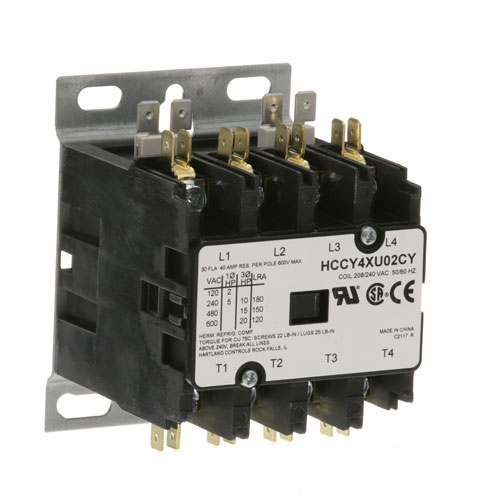

Jackson 05945-109-01-69 Dishmachine Contactor 4 Pole 30/40A 208/240V
Specifications:
- Hartland Contactor
- 4 Pole
- 208/240 Volt
- 30 Amp Inductive, 40 Amp Resistive
- Groen Steamer
- Vulcan Fryer, Kettle, Oven Et
Description
Dimensions:
- Weight: 1.8 lbs
- Length: 3.13 in
- Height: 3 in
- Width: 4 in
CHAMPION:
HOBART:
00-346466-00014 00-346466-12 00-411497-000D3 111497-D3 24150-1 346466-12 346466-14 411497-000D3 411497-D3 HOB00-346466-12 HOB346466-12 HOBXNC6X127 XNC6X127 XNC6X127/346466-12 XNC6X129/346466-14
LANG:
STAR MFG:
VULCAN HART:
00-346466-00014 00-411497-000D3 111497-D3 24150-1 346466-14 411497-000D3 411497-D3
Step1: Turn off main power and verify zero voltage with tester
Step2: Mount contactor on DIN rail or panel securely
Step3: Connect load and line wires to correct terminals per wiring diagram
Step4: Tighten terminal screws firmly
Step5: Connect control coil supply
Step6: Restore power and test operation ensuring correct function insulation and grounding
Step7: Wear PPE and ensure cover is closed before energizing circuit for safety always
-
What maintenance is required for the Jackson 05945-109-01-69 Contactor?
Inspect the contactor periodically for signs of pitting, arcing, or burnt contacts that can affect performance. Ensure all electrical terminals are tight and free from corrosion to maintain stable conductivity. Keep the enclosure clean and dry to prevent moisture-related failures.
-
What are common issues with the Jackson 05945-109-01-69 Contactor?
- Contact pitting or burning from electrical arcing.
- Coil failure preventing activation.
- Intermittent switching or chattering.
- Voltage drop causing inaccurate operation.
- Mechanical wear leading to stuck contacts.
Customer Reviews
No reviews yet. Be the first to write one!
Write a Review
We strive to provide our customers with a hassle-free and efficient shopping experience. Our shipping policy ensures the timely delivery of your orders and complete customer satisfaction. View More
We are committed to ensuring your complete satisfaction with every purchase. We understand that circumstances may arise where you must return a product or request a refund. If for any reason you are not satisfied, you may return the item(s) according to the terms outlined below. View More
This Payment Policy outlines the terms and conditions governing all payments made for products purchased through our website. By making a purchase, you agree to be bound by this Payment Policy. View More