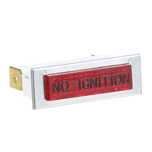
Hobart 354575-00004 Control Panel Red Signal Light 28V
Specifications:
- Red Signal Light, "No Ignition", 3/8" X 1-5/16", Flat,
- 1/4" Tabs, 28V, Chrome Bezel, Lock Tabs,
- Vulcan Oven Gco2C, Gco2D, Gco4C, Gco4D, Gco4S, Sg4C, Sg4D,
- Sg6C, Sg6D, Vc4Gc, Vc4Gd, Vc4Gs, Vc6Gc, Vc6Gd, Vc6Gs
- Wolf Oven Wkef, Wkgf
Description
Dimensions:
- Weight: 0.1 lbs
- Length: 1.38 in
- Height: 1 in
- Width: 0.5 in
HOBART:
00-354575-00004 00-354575-4 354575-4 HOB00-354575-4 HOB354575-4
VULCAN HART:
Step1: Switch off power and verify the equipment is completely de-energized before opening the panel.
Step2: Remove the cover to access the existing indicator light assembly.
Step3: Disconnect the old light wiring, keeping track of terminal positions.
Step4: Fit the new signal light into the mounting opening and secure it firmly.
Step5: Reconnect wiring, restore power, and confirm proper illumination during operation.
-
What maintenance is required for the Hobart 354575-00004 Signal Light?
Inspect the signal light regularly for proper illumination and ensure the lens is clean and free of grease or debris. Check wiring connections for tightness and signs of corrosion or heat damage. Replace the bulb or assembly if dimming, flickering, or complete failure occurs. Ensure the mounting remains secure to avoid vibration-related issues.
-
What are common issues with the Hobart 354575-00004 Signal Light?
- Bulb burnout leading to no illumination.
- Flickering caused by loose wiring or weak electrical contact.
- Lens discoloration reducing visibility of indicator.
- Intermittent operation due to connection failures.
- Heat damage affecting internal components.
Customer Reviews
No reviews yet. Be the first to write one!
Write a Review
We strive to provide our customers with a hassle-free and efficient shopping experience. Our shipping policy ensures the timely delivery of your orders and complete customer satisfaction. View More
We are committed to ensuring your complete satisfaction with every purchase. We understand that circumstances may arise where you must return a product or request a refund. If for any reason you are not satisfied, you may return the item(s) according to the terms outlined below. View More
This Payment Policy outlines the terms and conditions governing all payments made for products purchased through our website. By making a purchase, you agree to be bound by this Payment Policy. View More