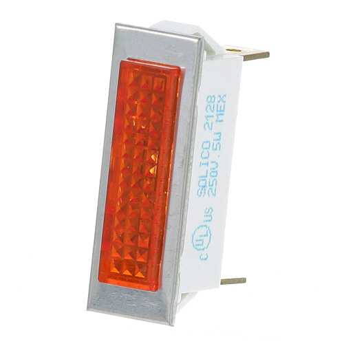
Southbend 4996-5 Range Signal Light Amber 3/8" X 1-5/16" 250V
Specifications:
- Signal Light
- 250 V [ Fits Hole 3/8" X 1-5/16" ] [ 1/4" Tabs ] [Color
- Amber] [ Type Hat Flat ][ Bezel Chrome] [ Fastener Lock
- Tabs]
- Cleveland Skillet Set-10, Sel, Sem
- Southbend
Description
Dimensions:
- Weight: 0.1 lbs
- Length: 1.38 in
- Height: 1 in
- Width: 0.5 in
Step1: Disconnect power and carefully confirm zero voltage before installation to ensure safety.
Step2: Insert signal light into the panel cutout and align it correctly.
Step3: Secure using the mounting bezel until snug.
Step4: Connect wiring leads to the proper control circuit terminals, observing polarity.
Step5: Insulate and route wires away from heat sources or moving parts.
Step6: Restore power and test for proper illumination before use.
-
What maintenance is required for the Southbend 4996-5 Signal Light?
Regularly clean the lens to ensure clear signal visibility and prevent residue buildup. Check electrical connections for tightness and corrosion. Inspect mounting stability in high-heat conduction. Replace worn or damaged parts to ensure consistent signaling performance.
-
What are common issues with the Southbend 4996-5 Signal Light?
- Intermittent or flickering light output.
- Bulb or diode burnout.
- Loose wiring connections.
- Overheating causing reduced performance.
- Moisture inside housing.
- Dimming due to electrical wear.
Customer Reviews
Write a Review
-
Very Durable
Bright and clear, highly recommend
We strive to provide our customers with a hassle-free and efficient shopping experience. Our shipping policy ensures the timely delivery of your orders and complete customer satisfaction. View More
We are committed to ensuring your complete satisfaction with every purchase. We understand that circumstances may arise where you must return a product or request a refund. If for any reason you are not satisfied, you may return the item(s) according to the terms outlined below. View More
This Payment Policy outlines the terms and conditions governing all payments made for products purchased through our website. By making a purchase, you agree to be bound by this Payment Policy. View More