
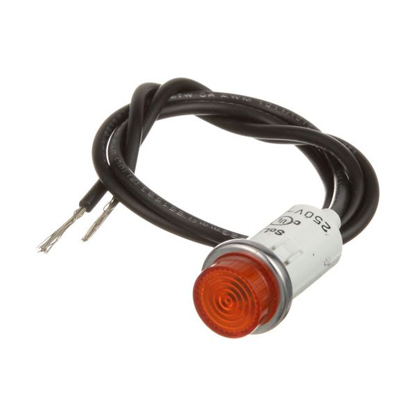
APW 2E-63012 Amber Signal Light W/1/2" Hole 250V

$15.44
Out of stock
SKU
2E-63012
Manufacturer:

The APW 2E-63012 Amber Signal Light operates by reflecting up when electrical current is passing through the internal element, which means that a control circuit in the equipment is active when it is in operation. It consumes a little bit of power to keep it lit when it is attached to the wiring of the system. It is mounted on the front panel of foodservice equipment in a 1/2" hole. This amber indicator is designed to run on 250 volts, and it will give a visible indication of electrical activity.

Dimensions

  • Length: 0.5 In
  • Width: 0.5 In
  • Height: 1.2 In
  • Weight: 0.1 lbs
https://partsfe.com/media/catalog/product/a/p/apw-2e-63012-250v-amber-signal-light-with-1-2-hole-28680-2.jpg

Product Notes

  • Signal Light
  • 250V [ Fits Hole 1/2" ] [10" Leads ] [Color Amber] [
  • Type Hat Raised/Flat ][ Bezel Chrome] [ Fastener Lock Tabs]
  • American Permanent Ware
  • Hot Dog Steamer Ds-1A, S/N 900500 & Up
  • Hot Plate Cp-155, Cp-240
  • Warmer & Toaster Where Applicable.
  • Duke/Franklin Thermotainer
  • Franklin Chef Warmer
  • Garland Grill, Oven
  • Southbend Steamer 2001/Dual Power~
  • R-1 (After 1/91).
APW WYOTT:
2E-56530, 2E-56536, 2E-63012, 45653000, 56530, 56536, 63012, APW45653000, APW63012
GARLAND:
SOUTHBEND:
TAYLOR FREEZER:
017450
Write Your Own Review
You're reviewing:APW 2E-63012 Amber Signal Light W/1/2" Hole 250V
Your Rating
Customer Questions
No Questions

We strive to provide our customers with a hassle-free and efficient shopping experience. Our shipping policy ensures the timely delivery of your orders and complete customer satisfaction. View More

We are committed to ensuring your complete satisfaction with every purchase. We understand that circumstances may arise where you must return a product or request a refund. If for any reason you are not satisfied, you may return the item(s) according to the terms outlined below. View More

This Payment Policy outlines the terms and conditions governing all payments made for products purchased through our website. By making a purchase, you agree to be bound by this Payment Policy. View More

Installation Steps

Step1: Turn off power supply and confirm zero voltage using a tester before beginning work.

Step2: Drill or check panel hole is clean and properly sized for secure fit.

Step3: Insert signal light into panel opening and tighten mounting nut until firmly secured.

Step4: Connect electrical leads according to wiring diagram, ensuring correct voltage rating and insulation.

Step5: Restore power and test indicator operation, checking for steady illumination and safe operation.