
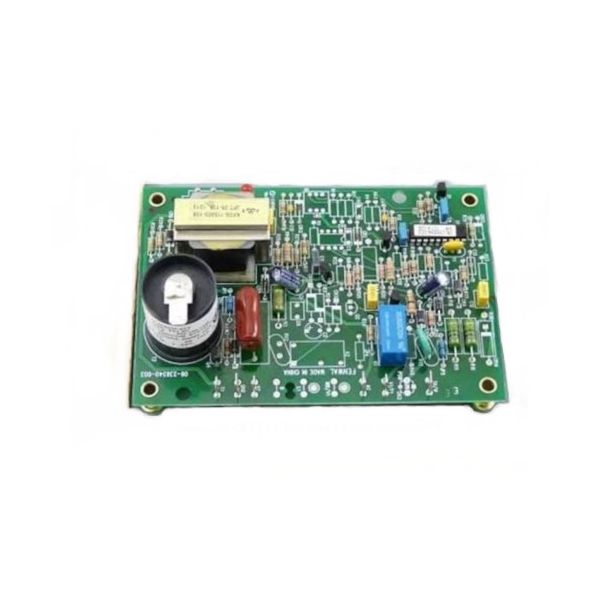
Hobart 424137-00002 Ignition Control Board 24VAC 3-3/4" X 5-1/2"

Special Price $188.94 Regular Price $291.12
In stock
SKU
424137-00002
The Hobart 424137-00002 Ignition Control Board is used in cooking equipment to provide ignition and control of gas-fired systems. Measuring 3-3/4” x 5-1/2”, this control board is designed to work with a 24VAC power supply to control ignition sequence and flame sensor check. It also assists in avoiding ignition failures, cuts on time wastage, and increases the durability of your tools. Perfect for ovens and other gas appliances, the ignition control board offers accurate and steady performance, which makes cooking more secure and energy-saving in the kitchen and saves time.

Dimensions

  • Length: 5.5 In
  • Width: 3.75 In
  • Height: 2 In
  • Weight: 0.8 lbs
https://partsfe.com/media/catalog/product/h/o/hobart-424137-00002-ignition-control-board-24vac-3-3-4-x-5-1-2-23192-2.jpg

Product Notes

  • Ignition Control Board,24Vac
  • 3-3/4" X 5-1/2" Control Board, Fenwal
  • Vulcan Oven Sg4C, Sg4D, Sg6C, Sg6D, Vc4G(D,S)
Write Your Own Review
You're reviewing:Hobart 424137-00002 Ignition Control Board 24VAC 3-3/4" X 5-1/2"
Your Rating
Customer Questions
What maintenance is required for the Hobart 424137-00002 Ignition Control Board?

Inspect the ignition control board for dust, moisture, and loose wiring. Keep connections tight and dry. Ensure proper grounding and avoid overheating to maintain stable ignition performance and efficient burner startup.

What are common issues with the Hobart 424137-00002 Ignition Control Board?

  • Failure to initiate ignition sequence in equipment.
  • Intermittent burner startup or no spark output.
  • Burnt components due to electrical surges.
  • Loose or corroded wiring connections.
  • Overheating causing system shutdown or resets.

We strive to provide our customers with a hassle-free and efficient shopping experience. Our shipping policy ensures the timely delivery of your orders and complete customer satisfaction. View More

We are committed to ensuring your complete satisfaction with every purchase. We understand that circumstances may arise where you must return a product or request a refund. If for any reason you are not satisfied, you may return the item(s) according to the terms outlined below. View More

This Payment Policy outlines the terms and conditions governing all payments made for products purchased through our website. By making a purchase, you agree to be bound by this Payment Policy. View More

Installation Steps

Step1: Disconnect power and gas supply confirm zero voltage for safety.

Step2: Remove access panel and note wiring connections, inspect wiring harness carefully.

Step3: Disconnect and label wires from old ignition control board for correct reconnection.

Step4: Mount the new control board securely in position, ensuring proper alignment.

Step5: Reconnect wiring according to schematic diagram per manufacturer diagram.

Step6: Restore power, test ignition sequence, and verify safe flame operation, ensure no gas leaks.