
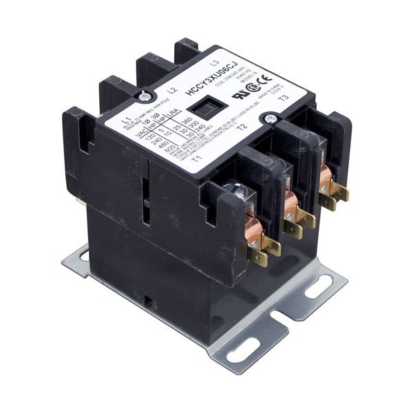
Hubbell C25FNF360B 3-Pole Contactor 208/240V 60 AMP Inductive/75 AMP Resistive

Special Price $168.74 Regular Price $260.00
In stock
SKU
C25FNF360B
Manufacturer:

Hubbell C25FNF360B 3 Pole Contactor provides dependable electrical control for heavy duty applications making it ideal for improve kitchen and food service equipment. This contactor operates at 208/240V along with has a 60 AMP inductive and 75 AMP resistive load capacity to ensure stability under rigorous operating circumstances. This partstands out because it provides effortless compatibility with Hartland contactors and steamers and improveers and steam generators which makes it suitable for diverse operational requirements. This product has simple installation and maintenance because it measures 3" x 4" x 3.5".

Dimensions

  • Length: 4 In
  • Width: 3 In
  • Height: 3.5 In
  • Weight: 1.8 lbs
https://partsfe.com/media/catalog/product/h/u/hubbell-c25fnf360b-3-pole-contactor-208-240v-60-amp-inductive-75-amp-resistive-97125-2.jpg

Product Notes

  • Hartland Contactor
  • 3 Pole
  • 208/240 Volt
  • 60 Amp Inductive
  • 75 Amp Resistive
  • Cleveland Steamer
  • Hubbel Booster
  • Legion Kettle
  • Market Forge Steam Generators
ACCUTEMP:
CLEVELAND:
CROWN STEAM:
HUBBELL:
LEGION:
MIDDLEBY MARSHALL:
VULCAN HART:
Write Your Own Review
You're reviewing:Hubbell C25FNF360B 3-Pole Contactor 208/240V 60 AMP Inductive/75 AMP Resistive
Your Rating
Customer Questions
What maintenance is required for the Hubbell C25FNF360B Contactor?

Inspect contact points regularly for pitting, burning, or excessive wear caused by load switching. Tighten all electrical terminals to prevent overheating and voltage drop. Verify coil operation and rated voltage during service checks. Keep the enclosure clean and dry to avoid contamination and arcing issues.

What are common issues with the Hubbell C25FNF360B Contactor?

  • Contact welding from overload or excessive inrush current.
  • Coil failure leading to no switching operation.
  • Chattering due to low or unstable control voltage.
  • Burned or pitted contacts causing high resistance.
  • Overheating from loose terminals or heavy load conditions.

We strive to provide our customers with a hassle-free and efficient shopping experience. Our shipping policy ensures the timely delivery of your orders and complete customer satisfaction. View More

We are committed to ensuring your complete satisfaction with every purchase. We understand that circumstances may arise where you must return a product or request a refund. If for any reason you are not satisfied, you may return the item(s) according to the terms outlined below. View More

This Payment Policy outlines the terms and conditions governing all payments made for products purchased through our website. By making a purchase, you agree to be bound by this Payment Policy. View More

Installation Steps

Step1: Turn off main power supply and check zero voltage with a multimeter before servicing.

Step2: Open electrical enclosure and label existing line/load/control wires for correct reconnection.

Step3: Remove old contactor by loosening terminal screws and mounting hardware.

Step4: Mount new contactor securely onto DIN rail or panel bracket.

Step5: Reconnect line, load, and coil control wiring tightly to correct terminals.

Step6: Restore power and test switching operation under load for proper connect.