
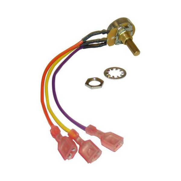
Garland GL1955601 Potentiometer W/3 EA 1/4" Female Push-Ons 3-Wire Leads

Special Price $74.63 Regular Price $166.44
In stock
SKU
GL1955601
The Garland GL1955601 Potentiometer 3 Wire Leads W/3 EA 1/4 Female Push-Ons is a resistor that is used to control the voltage or signal levels in an appliance control circuit by changing the electrical conductivity of the part. The internal shaft varies the signal sent to the other components connected to it as it rotates, enabling the operation to be varied. This is mounted at the back of a control panel and linked to knobs, switches or electronic boards in commercial cooking equipment.

Dimensions

  • Length: 4 In
  • Width: 1 In
  • Height: 5 In
  • Weight: 0.1 lbs
https://partsfe.com/media/catalog/product/g/a/garland-gl1955601-potentiometer-3-wire-leads-w-3-ea-1-4-female-push-ons-40279-2.jpg

Product Notes

  • Potentiometer, 3 Wire Leads W/ 3 Ea 1/4" Female Push-Ons,
  • Garland
  • Mco-E5, Mco-Es-10-S, Mco-Es-10A, Mco-Es-Ed-10, Mco-G-5,
  • Mco-Gd-20-S, Mco-Gs-10Arby, Mco-Gs-20Arby, Mco-Gs/Gd-10,
  • Mcoe5Ldsmd, Mp-Es/Ed-10, Mp-Gs/Gd-10
  • For 200 Series
Write Your Own Review
You're reviewing:Garland GL1955601 Potentiometer W/3 EA 1/4" Female Push-Ons 3-Wire Leads
Your Rating
Customer Questions
What maintenance is required for the Garland GL1955601 Potentiometer?

Keep the potentiometer clean and free from dust or grease buildup. Inspect for smooth adjustment and check connections. Routine care supports accurate control settings and secure electrical performance.

What are common issues with the Garland GL1955601 Potentiometer?

  • Inconsistent output signal during adjustment.
  • Erratic control response affecting settings.
  • Wear on internal components reducing accuracy.
  • Electrical noise interfering with performance.
  • Loose connections causing instability.
  • Difficulty adjusting smoothly.

We strive to provide our customers with a hassle-free and efficient shopping experience. Our shipping policy ensures the timely delivery of your orders and complete customer satisfaction. View More

We are committed to ensuring your complete satisfaction with every purchase. We understand that circumstances may arise where you must return a product or request a refund. If for any reason you are not satisfied, you may return the item(s) according to the terms outlined below. View More

This Payment Policy outlines the terms and conditions governing all payments made for products purchased through our website. By making a purchase, you agree to be bound by this Payment Policy. View More

Installation Steps

Step1: Disconnect power before installation.

Step2: Remove the old potentiometer by loosening mounting screws.

Step3: Install the new potentiometer in the same orientation.

Step4: Reconnect wiring and ensure secure connections.

Step5: Restore power and test performanceality.