
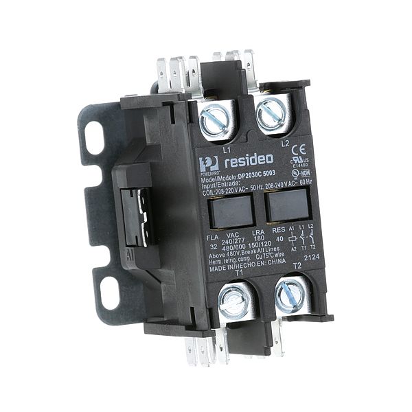
Jackson 5945-002-74-20 Contactor 2-Pole W/1/4" Male Tab Terminals & 1-5/8" MT CTRS 208/240V

Special Price $47.03 Regular Price $65.86
In stock
SKU
5945-002-74-20
Manufacturer:

The Jackson 5945-002-74-20 Contactor works on the concept of opening and closing the two-pole contacts of the component by means of an electromagnetic coil to regulate the flow of electricity in a circuit. Applying voltage to the coil produces a magnetic field, which causes the contacts to be pulled together to allow the transmission of current and the release of the contacts to de-energize the coil. This component can be installed in electrical panels or equipment in which 208/240V circuits need to be switched under control and connected through 1/4" male tab terminals and mounted on 1-5/8" mounting centers.

Dimensions

  • Length: 4.5 In
  • Width: 3.5 In
  • Height: 3 In
  • Weight: 0.54 lbs
https://partsfe.com/media/catalog/product/j/a/jackson-5945-002-74-20-2-poles-2-poles-w-1-4-male-tab-terminals-1-5-8-mt-ctrs-208-240v-23828-2.jpg

Product Notes

  • Relay, [ 2 Poles] [30 Amps] [208/240V ]
  • [ 1/4" Male Tab Terminals] [ 1-5/8" Mt Ctrs ] [Honeywell ]
  • Jackson Dishwasher 10, 24
Write Your Own Review
You're reviewing:Jackson 5945-002-74-20 Contactor 2-Pole W/1/4" Male Tab Terminals & 1-5/8" MT CTRS 208/240V
Your Rating
Customer Questions
What maintenance is required for the Jackson 5945-002-74-20 Contactor?

Regularly inspect the contact points for excessive pitting or carbon buildup to ensure accurate electrical conductivity. Tighten the tab terminal connections to prevent overheating from high resistance. Always discharge power before cleaning the housing of dust or debris to maintain optimal safety and performance.

What are common issues with the Jackson 5945-002-74-20 Contactor?

  • Burnt or welded contact points due to electrical arcing.
  • Audible humming or buzzing caused by a failing magnetic coil.
  • Intermittent power delivery from loose or corroded terminal connections.
  • Failure to connect or disconnect under load.

We strive to provide our customers with a hassle-free and efficient shopping experience. Our shipping policy ensures the timely delivery of your orders and complete customer satisfaction. View More

We are committed to ensuring your complete satisfaction with every purchase. We understand that circumstances may arise where you must return a product or request a refund. If for any reason you are not satisfied, you may return the item(s) according to the terms outlined below. View More

This Payment Policy outlines the terms and conditions governing all payments made for products purchased through our website. By making a purchase, you agree to be bound by this Payment Policy. View More

Installation Steps

Step1: Turn off power at breaker and check absence of voltage with a tester.

Step2: Mount switch usingin centers and secure firmly in panel.

Step3: Connect male tab terminals to matching female connectors, ensuring tight fit.

Step4: Secure wiring, avoid strain, and insulate exposed conductors properly.

Step5: Restore power and test operation safely for safe operation.

Step6: Do not touch live terminals ensure grounding and compliance with electrical codes.