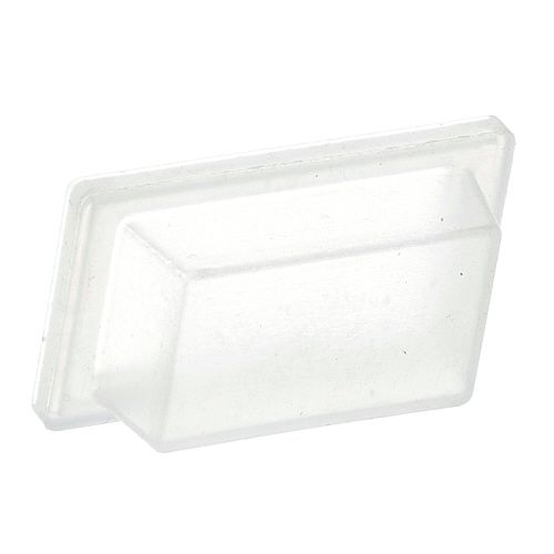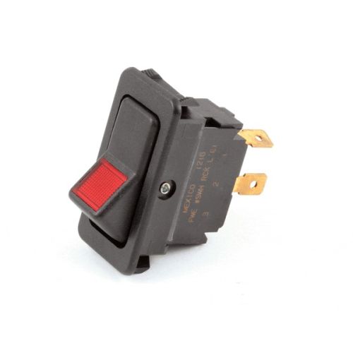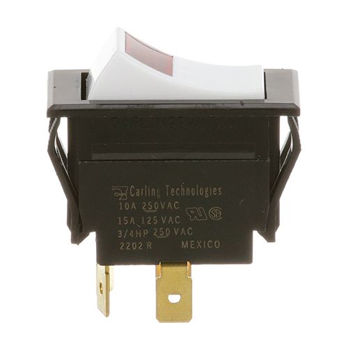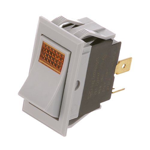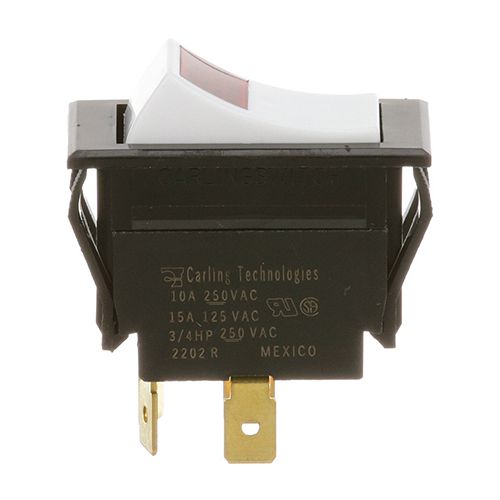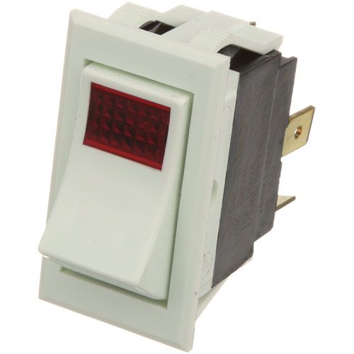
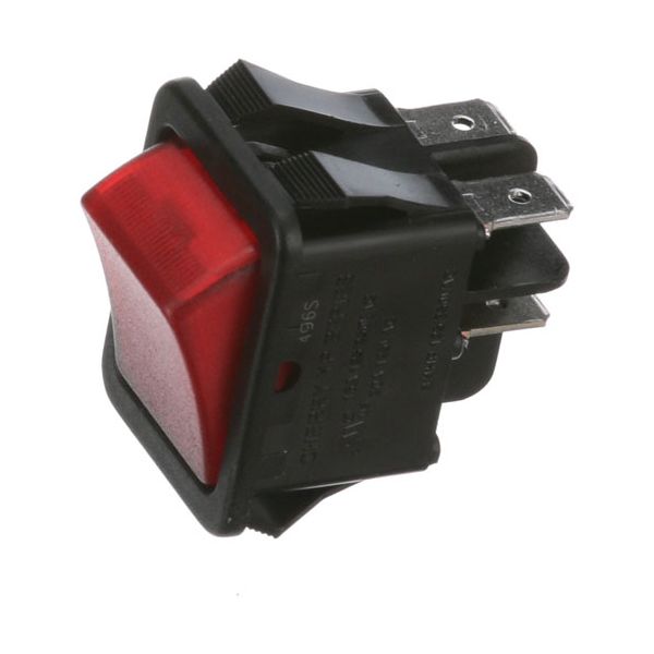
Randell ELSWT610BE Rocker Switch Red Lighted DPST 20A/125 VAC

Special Price $18.70 Regular Price $26.72
In stock
SKU
ELSWT610BE
Manufacturer:

The Randell ELSWT610BE Rocker Switch Red Lighted 20A/125 Vac DPST completes or interrupts two electrical circuits when the rocker is operated, enabling current to pass through both poles or interrupting it as required. When the switch is on, the integrated red light goes on, and this means that the circuits are on. It fits in the control panel of an appropriate piece of equipment and is installed with a cutout that has terminals to which wiring connections can be made. The double-pole/single-throw design facilitates the coordinated operation of two or more circuits using one switch actuator.

Dimensions

  • Length: 1.5 In
  • Width: 1.25 In
  • Height: 1 In
  • Weight: 0.25 lbs
https://partsfe.com/media/catalog/product/r/a/randell-elswt610be-dpst-red-lighted-rocker-switch-20a-125vac-39318-2.jpg

Product Notes

  • Red Lighted, Dpst, 20A/125Vac
RANDELL:
Write Your Own Review
You're reviewing:Randell ELSWT610BE Rocker Switch Red Lighted DPST 20A/125 VAC
Your Rating
Customer Questions
What maintenance is required for the Randell ELSWT610BE Rocker Switch?

Keep the rocker switch free of dust and debris and periodically inspect terminals for looseness or corrosion. Proper maintenance ensures accurate switching performance and prevents electrical faults. Always disconnect power before inspection and avoid moisture exposure for safety.

What are common issues with the Randell ELSWT610BE Rocker Switch?

  • Intermittent switching or failure to engage contacts under load.
  • Light indicator not illuminating due to internal LED failure.
  • Loose terminal connections causing power interruption.
  • Contact wear leading to inconsistent conductivity.

We strive to provide our customers with a hassle-free and efficient shopping experience. Our shipping policy ensures the timely delivery of your orders and complete customer satisfaction. View More

We are committed to ensuring your complete satisfaction with every purchase. We understand that circumstances may arise where you must return a product or request a refund. If for any reason you are not satisfied, you may return the item(s) according to the terms outlined below. View More

This Payment Policy outlines the terms and conditions governing all payments made for products purchased through our website. By making a purchase, you agree to be bound by this Payment Policy. View More

Installation Steps

Step1: Turn off power at breaker to secure from electric shock.

Step2: Cut panel opening and confirm old switch fit.

Step3: Connect line and load wires to terminals per wiring diagram, tightening securely.

Step4: Align the new switch into panel until firmly seated.

Step5: Restore power and test illumination and switching operation.