
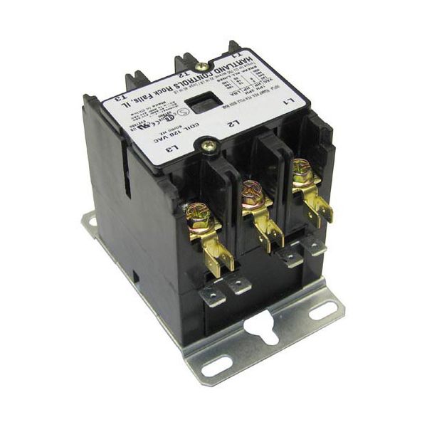
Curtis WC-431 3-Pole Contactor 60 AMP Inductive/75 AMP Resistive

Special Price $151.46 Regular Price $233.38
In stock
SKU
WC-431
Manufacturer:

The Curtis WC-431 3-Pole Contactor is used for efficient electrical control in environments. The contactor functions as a 110/120 volt part that provides 60 amp inductive and 75 amp resistive load capacity for various equipment including coffee brewers and other heavy-duty appliances. This contactor stands out because of its durable build quality which provides dependable performance in challenging operating environments beyond typical contactor capabilities. The WC-431 functions with multiple models which enables smooth integration into existing system frameworks. The compact dimensions of 4.15 inches in length and 3.75 inches in width make this part suitable for installation while maintaining its powerful performance Features.

Dimensions

  • Length: 4 In
  • Width: 3 In
  • Height: 3.5 In
  • Weight: 1.8 lbs
https://partsfe.com/media/catalog/product/c/u/curtis-wc-431-3-pole-contactor-60-amp-inductive-75-amp-resistive-15695.jpg

Product Notes

  • Hartland Contactor
  • 3 Pole
  • 110/120 Volt
  • 60 Amp Inductive
  • 75 Amp Resistive
BLODGETT:
CHAMPION:
CLEVELAND:
CROWN STEAM:
CURTIS:
SOUTHBEND:
Write Your Own Review
You're reviewing:Curtis WC-431 3-Pole Contactor 60 AMP Inductive/75 AMP Resistive
Your Rating
Customer Questions
What maintenance is required for the Curtis WC-431 Contactor?

Inspect contacts periodically for wear, burning, or surface damage and clean using a proper electrical contact cleaner. Ensure all terminal connections remain tight to avoid resistance buildup and overheating. Routine inspection helps maintain stable switching performance and reduces electrical faults in applications.

What are common issues with the Curtis WC-431 Contactor?

  • Contact surface erosion.
  • Coil damage resulting in failure to energize.
  • Contacts sticking in closed position under load.
  • Irregular switching due to unstable voltage supply.
  • Excess heat buildup.

We strive to provide our customers with a hassle-free and efficient shopping experience. Our shipping policy ensures the timely delivery of your orders and complete customer satisfaction. View More

We are committed to ensuring your complete satisfaction with every purchase. We understand that circumstances may arise where you must return a product or request a refund. If for any reason you are not satisfied, you may return the item(s) according to the terms outlined below. View More

This Payment Policy outlines the terms and conditions governing all payments made for products purchased through our website. By making a purchase, you agree to be bound by this Payment Policy. View More

Installation Steps

Step1: Disconnect all power and verify zero voltage with a tester for safety.

Step2: Mount the contactor securely on a DIN rail or panel surface.

Step3: Connect line and load terminals according to wiring diagram.

Step4: Wire coil control terminals with correct voltage rating.

Step5: Tighten all connections to manufacturer torque specifications.

Step6: Inspect for loose wires, short circuits, and proper insulation.

Step7: Restore power and test switching operation under no-load conditions.