
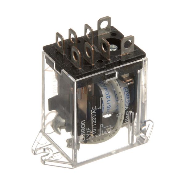
Hobart 416535-00006 Convection Oven Relay 10A 110/120V

Special Price $79.35 Regular Price $122.28
In stock
SKU
416535-00006
The Hobart 416535-00006 Convection Oven Relay 10A 110/120V switches electrical power through internal contacts by opening or closing when the control circuit activates the coil. When the voltage is applied, the relay coil gets activated and connects the input to the output to enable the flow of current to the controlled component and the contacts open to break the flow. It is installed in the electrical compartment of the equipment and is incorporated in the control wiring where circuits need to be switched. This relay is designed to be the one that does not operate in the usual manner of activation.

Dimensions

  • Length: 1.75 In
  • Width: 1 In
  • Height: 1.75 In
  • Weight: 0.2 lbs
https://partsfe.com/media/catalog/product/h/o/hobart-416535-00006-relay-10-amps-110-120v-25151-2.jpg

Product Notes

  • Relay, [10 Amps] [110/120V ] [ 8Ea 3/16" Male Terminals]
  • [1-1/2" Mt Ctrs ] [Omron ] Note: For 240V Use # 44-1435.
  • Vulcan Fryer Series Er, Erc225, Erc225F, Erc40, Erc40F,
  • Erc50, Erc50F, Erc85, Erc85F, Erd225, Erd225F, Erd40,
  • Erd40F, Erd50, Erd50F, Erd85, Erd85F,
  • Oven Sg4C, Sg4D, Sg6C, Sg6D, Vc4Gc, Vc4Gd, Vc4Gs, Vc6Gc,
  • Vc6Gd, Vc6Gs,
  • Convection Steamer C24Ga10, C24Ga6,
Write Your Own Review
You're reviewing:Hobart 416535-00006 Convection Oven Relay 10A 110/120V
Your Rating
Customer Questions
What maintenance is required for the Hobart 416535-00006 Relay?

Inspect the relay for signs of overheating, discoloration, or burnt contacts during routine checks. Keep the housing clean and free from dust or moisture buildup. Ensure terminals are tight and secure to maintain stable electrical switching and prevent intermittent control failures.

What are common issues with the Hobart 416535-00006 Relay?

  • Burnt or pitted contacts reducing conductivity.
  • Relay sticking or failing to switch.
  • Intermittent electrical operation.
  • Overheating during continuous load.
  • Loose terminals causing signal loss.

We strive to provide our customers with a hassle-free and efficient shopping experience. Our shipping policy ensures the timely delivery of your orders and complete customer satisfaction. View More

We are committed to ensuring your complete satisfaction with every purchase. We understand that circumstances may arise where you must return a product or request a refund. If for any reason you are not satisfied, you may return the item(s) according to the terms outlined below. View More

This Payment Policy outlines the terms and conditions governing all payments made for products purchased through our website. By making a purchase, you agree to be bound by this Payment Policy. View More

Installation Steps

Step1: Disconnect power supply and verify zero voltage for safety.

Step2: Remove access panel of equipment and locate old relay.

Step3: Carefully detach wiring terminals, noting positions for reconnection.

Step4: Install new relay in same orientation and secure firmly.

Step5: Reconnect wiring as noted and ensure tight connections.

Step6: Reassemble panel and restore power to test operation.