Blodgett 6502 Oven Rocker Switch Cook/Cool Down Red DPDT 7/8" X 1-1/2"

Special Price $26.45 Regular Price $43.92
Out of stock
SKU
6502
Manufacturer:
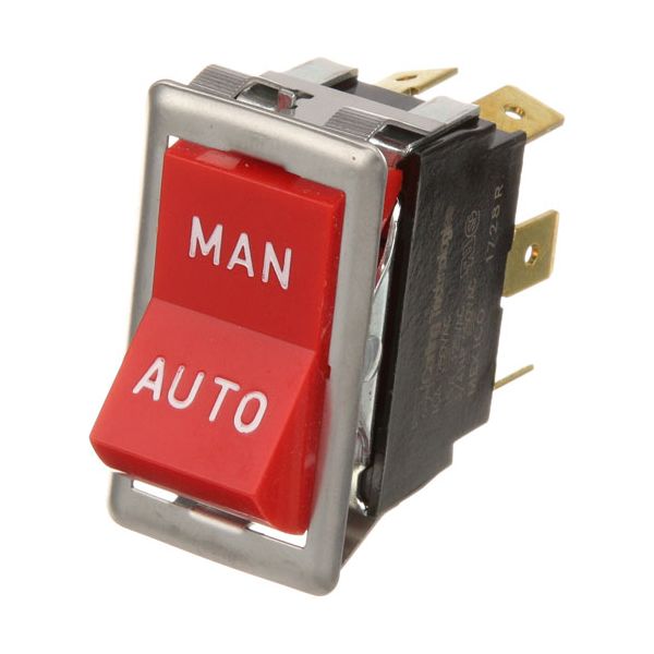
The Blodgett 6502 Oven Rocker Switch Cook/Cool Down Red DPDT 7/8" X 1-1/2" is a control switch that fits into the compatible commercial ovens to switch between cook and cool-down mode. This is a red, double-pole and double-throw rocker switch that fits into a panel cutout and connects with the control circuitry of the oven. In an actual kitchen application, it enables operators to choose the right mode in the baking process or after cooking. As part of the electrical system of the appliance.

Dimensions

  • Length: 1.5 In
  • Width: 0.875 In
  • Height: 2.5 In
  • Weight: 0.1 lbs
https://partsfe.com/media/catalog/product/b/l/blodgett-6502-red-rocker-switch-dpdt-15a-125v-10a-250v-fits-7-8-x-1-1-2-hole-65126-2.jpg

Product Notes

  • [ Red Rocker Switch ] [ Fits Hole 7/8 X 1-1/2 ] [ On/On ] [
  • Dpdt ] [ Terminals 6 (1/4" Tabs) ] [ 15A/125V,10A/250V ]
  • [ Color Red/Chrome Bezel ]
  • [ Markings Man/Auto ] Cool Down
  • Blodgett
  • Oven Series: Bcg, Ctb, Ctbr, Ef/Eze, Fa/Gzl, Re.
  • Zephaire E & G W/Solid State Controls.
  • *For 208V Units*
BLODGETT:
Write Your Own Review
You're reviewing:Blodgett 6502 Oven Rocker Switch Cook/Cool Down Red DPDT 7/8" X 1-1/2"
Your Rating
Customer Questions
What maintenance is required for the Blodgett 6502 Rocker Switch?

Regularly inspect the switch contacts regularly for wear or pitting and ensure secure electrical connections to prevent arcing. Keep the component free from dust and moisture buildup. Use proper voltage ratings to avoid overload and ensure safe operation.

What are common issues with the Blodgett 6502 Rocker Switch?

  • Contact wear or arcing under frequent load.
  • Rocker switch sticking or inconsistent actuation.
  • Electrical connection loosening causing intermittent power.
  • Overheating when used beyond rated voltage/current.
  • Internal contact corrosion in humid environments.

We strive to provide our customers with a hassle-free and efficient shopping experience. Our shipping policy ensures the timely delivery of your orders and complete customer satisfaction. View More

We are committed to ensuring your complete satisfaction with every purchase. We understand that circumstances may arise where you must return a product or request a refund. If for any reason you are not satisfied, you may return the item(s) according to the terms outlined below. View More

This Payment Policy outlines the terms and conditions governing all payments made for products purchased through our website. By making a purchase, you agree to be bound by this Payment Policy. View More

Installation Steps

Step1: Disconnect power supply before starting to prevent electrical shock.

Step2: Insert switch into mounting cutout and secure.

Step3: Connect wiring to terminals according to circuit diagram carefully.

Step4: Tighten terminals firmly to ensure solid contact and proper connection.

Step5: Restore power and test switch operation under normal load.