Turbo Air P0143N0100 Refrigerator Main PCB

Special Price $243.99 Regular Price $568.95
In stock
SKU
P0143N0100
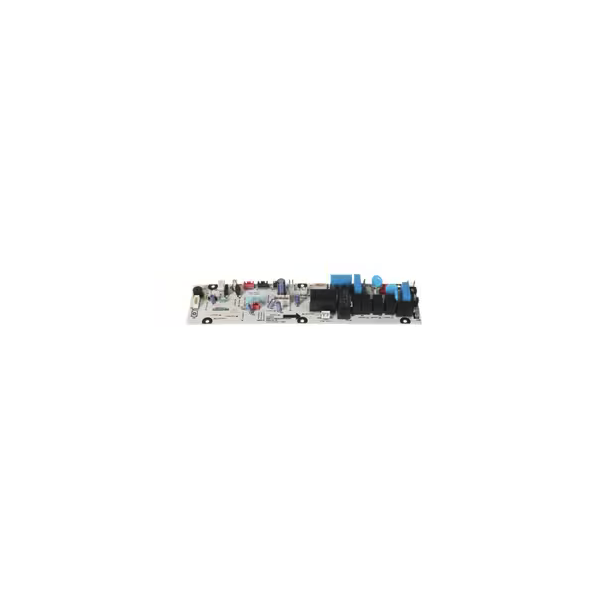
The Turbo Air P0143N0100 Refrigerator Main PCB is the electrical controller that processes the input signals and also manages the electrical power distribution to the connected parts of the system. It receives sensor and switch commands to facilitate communication between electric circuits and to facilitate normal operating functions. It serves as a central control unit for functions like temperature control, compressor control, and fans. It is used to combine with factory-specified systems and provides structured electrical control during the operations and maintenance of the equipment.

Dimensions

  • Length: 1 In
  • Width: 1 In
  • Height: 1 In
  • Weight: 0 lbs
https://partsfe.com/media/catalog/productno_selection
Write Your Own Review
You're reviewing:Turbo Air P0143N0100 Refrigerator Main PCB
Your Rating
Customer Questions
What maintenance is required for the Turbo Air P0143N0100 Main PCB?

Regularly inspect the PCB for dust, moisture, or burn marks. Clean gently with a dry, anti-static cloth to prevent short circuits. Proper ventilation in the appliance and check for loose wiring. Always disconnect power before handling to avoid electric shock.

What are the common issues with the Turbo Air P0143N0100 Main PCB?

  • ilure to control connected components correctly
  • Intermittent power or signal issues
  • Burned or damaged traces from electrical surges
  • Loose or corroded connectors
  • Erratic or unresponsive display or indicators,

We strive to provide our customers with a hassle-free and efficient shopping experience. Our shipping policy ensures the timely delivery of your orders and complete customer satisfaction. View More

We are committed to ensuring your complete satisfaction with every purchase. We understand that circumstances may arise where you must return a product or request a refund. If for any reason you are not satisfied, you may return the item(s) according to the terms outlined below. View More

This Payment Policy outlines the terms and conditions governing all payments made for products purchased through our website. By making a purchase, you agree to be bound by this Payment Policy. View More

Installation Steps

Step1: Disconnect the unit from power and follow proper lockout/tagout procedures before servicing.

Step2: Remove the rear or control access panel to expose the existing PCB.

Step3: Disconnect wiring harnesses and grounding wires from the old board.

Step4: Unscrew the mounting fasteners and carefully remove the damaged PCB.

Step5: Install the new board, secure it with screws, and reconnect all wiring as labeled.

Step6: Reinstall the access panel, restore power, and test the unit for proper operation.