Southbend 4344-1 Gas Tilting Skillet Thermocouple 48" Long Ring Terminal End

Special Price $202.41 Regular Price $240.74
In stock
SKU
4344-1
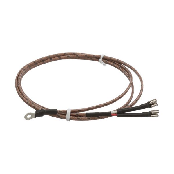
The Southbend 4344-1 Gas Tilting Skillet Thermocouple is a temperature sensor that recognizes the variations in heat and transforms them into an electrical signal to make sure that the burner is turned on when it should be. The length of 48" enables it to reach the right connection point, and the ring terminal end helps in its safe attachment to the control system. It is designed to be installed in a gas tilting skillet, and it is placed in a position where it can monitor the flame, and it is directly connected to the burner assembly.

Dimensions

  • Length: 3 In
  • Width: 3 In
  • Height: 0.25 In
  • Weight: 0.4 lbs
https://partsfe.com/media/catalog/product/s/o/southbend-4344-1-thermocouple-48-long-ring-terminal-end-50371-2.jpg

Product Notes

  • Thermocouple, 48" Long. Ring Terminal One End And Two 1/4"
  • Female Disconnects On Other End. Red And White Wire.
  • Fits Southbend Models~
  • Fits Market Forge Models~
  • 30P-Stgl, 30P-Stgm, 40P-Stgl, 40P-Stgm, F-100L, F-100P,
  • F-20L, F-20P, F-30L, F-30P, F-40L, F-40P, F-60L, F-60P,
  • F-80L, F-80P, Ft-100L, Ft-100P, Ft-20L, Ft-20P, Ft-30L,
  • Ft-30P, Ft-40L, Ft-40P, Ft-60L, Ft-60P, Ft-80L, Ft-80P
More Information
Disable SaleableNo
ACCUTEMP:
BLODGETT:
CROWN STEAM:
MARKET FORGE:
SOUTHBEND:
VULCAN HART:
Write Your Own Review
You're reviewing:Southbend 4344-1 Gas Tilting Skillet Thermocouple 48" Long Ring Terminal End
Your Rating
Customer Questions
What maintenance is required for the Southbend 4344-1 Thermocouple?

Inspect for dirt, corrosion, or mechanical damage. Clean the tip gently and ensure secure wiring to the control system. Disconnect power and gas supply before servicing. Proper care ensures accurate temperature readings and safe operation.

What are the common issues with the Southbend 4344-1 Thermocouple?

  • Inaccurate temperature readings.
  • Intermittent signal loss or failure.
  • Corrosion or buildup on the probe tip.
  • Loose or damaged connectors affecting performance.

We strive to provide our customers with a hassle-free and efficient shopping experience. Our shipping policy ensures the timely delivery of your orders and complete customer satisfaction. View More

We are committed to ensuring your complete satisfaction with every purchase. We understand that circumstances may arise where you must return a product or request a refund. If for any reason you are not satisfied, you may return the item(s) according to the terms outlined below. View More

This Payment Policy outlines the terms and conditions governing all payments made for products purchased through our website. By making a purchase, you agree to be bound by this Payment Policy. View More

Installation Steps

Step1: Turn off gas and electrical supply, and allow unit to cool completely for safety.

Step2: Remove access panel to reach the pilot assembly.

Step3: Disconnect the faulty thermocouple from the control valve.

Step4: Insert and position the new thermocouple into the pilot bracket securely.

Step5: Tighten connections carefully, avoiding over-tightening or damage.

Step6: Restore supply and test ignition to confirm proper operation.

Step7: Wear heat-resistant gloves and check for gas leaks after installation.