
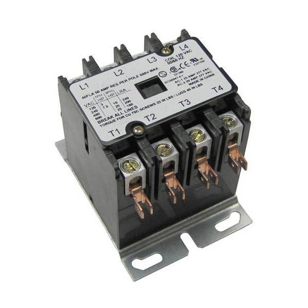
General Electric XNC6X130 4-Pole Contactor 110/120V 40/50A

Special Price $72.52 Regular Price $111.74
In stock
SKU
XNC6X130
The General Electric XNC6X130 4-Pole Contactor 110/120V 40/50A is an open and closed four-separate-contact system that uses an electromagnetic coil to regulate the flow of electrical current in a circuit. Upon the application of the voltage, the coil becomes active, drawing the contacts together to close the circuit and letting the electricity flow. The system is normally installed in electrical panels or control boxes, where it is connected to different circuits, and equipment and acts as a central control to control power flow and provide the ability to switch several lines at once.

Dimensions

  • Length: 3.125 In
  • Width: 4 In
  • Height: 3 In
  • Weight: 1.9 lbs
https://partsfe.com/media/catalog/product/g/e/general-electric-xnc6x130-4-pole-contactor-110-120v-40amp-21237.jpg

Product Notes

  • Hartland Contactor
  • 4 Pole
  • 110/120 Volt
  • 40 Amp Inductive
  • 50 Amp Resistive
Write Your Own Review
You're reviewing:General Electric XNC6X130 4-Pole Contactor 110/120V 40/50A
Your Rating
Customer Questions
What maintenance is required for the General Electric XNC6X130 Contactor?

Inspect contact points regularly for pitting or arcing damage. Keep terminals tight and free of corrosion to ensure accurate switching. Periodically clean dust and debris and verify coil voltage stability to prevent overheating.

What are common issues with the General Electric XNC6X130 Contactor?

  • Contact wear leading to intermittent switching.
  • Coil failure or burnout from voltage spikes.
  • Overheating due to overload or poor ventilation.
  • Mechanical sticking or welding of contacts.
  • Noisy operation/chatter due to unstable control voltage.

We strive to provide our customers with a hassle-free and efficient shopping experience. Our shipping policy ensures the timely delivery of your orders and complete customer satisfaction. View More

We are committed to ensuring your complete satisfaction with every purchase. We understand that circumstances may arise where you must return a product or request a refund. If for any reason you are not satisfied, you may return the item(s) according to the terms outlined below. View More

This Payment Policy outlines the terms and conditions governing all payments made for products purchased through our website. By making a purchase, you agree to be bound by this Payment Policy. View More

Installation Steps

Step1: Turn off all power supply and verify with tester.

Step2: Mount contactor securely on DIN rail or panel.

Step3: Connect load and line terminals as per wiring diagram.

Step4: Attach control coil terminals .

Step5: Tighten all terminal screws firmly.

Step6: Restore power and test switching operation.

Step7: Ensure enclosure is closed; follow electrical safety precautions and avoid live contact.