
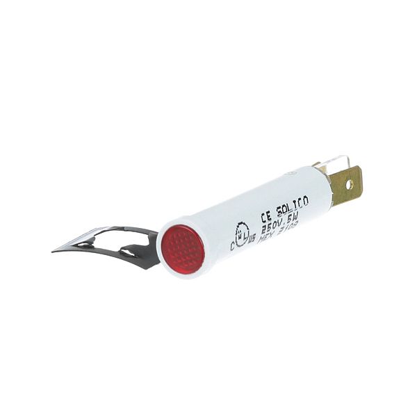
APW 1513903 Red Indicator Light 5/16" 250V

$5.70
In stock
SKU
1513903
The APW 1513903 Indicator Light 5/16" 250V is a red panel-mounted light used in foodservice and commercial cooking equipment to provide a visual indication of status. I have a chrome bezel and a 5/16" mounting hole with tab terminals to connect it electrically. The light is attached to the control panel of the appliance and is connected to the control circuit of the machine to turn on when a certain condition is met. It can be used as a visual indicator within the system to enable its users to determine the functioning states.

Dimensions

  • Length: 2 In
  • Width: 1 In
  • Height: 1 In
  • Weight: 0.006 lbs
https://partsfe.com/media/catalog/product/a/p/apw-1513903-5-16-chrome-bezel-red-indicator-light-w-3-16-tabs-94215-2.jpg
Manufacturer Name: APW
Product Number: 1513903
OEM Part Number: 1513903
Product Description: Indicator Light
Similar Models:2E-1513903 - APW
Dimensions:
Length:2in/5.08cm
Width:1in/2.54cm
Height:1in/2.54cm
Weight:0.006lbs/2.72g

Choose the best Commercial kitchen & Restaurant equipment parts and supplies from PartsFe!

  • Same Day Shipping

  • Best Quality And Best Price

  • Wide Range of Inventory

  • Best Customer Service

Have More Questions or Need Help to Place The Order?
Reach us at 866-863-0907 or contact@partsfe.com

GENERAL ELECTRIC:
HOBART:
00-342575-00001, 00-342575-1, 00-825100, 342575-00001, 342575-1, 824324-1, 825100, HOB00-342575-1, HOB342575-1, XNC25X89/342575-1
Write Your Own Review
You're reviewing:APW 1513903 Red Indicator Light 5/16" 250V
Your Rating
Customer Questions
What maintenance is required for the APW 1513903 Indicator Light?

Regularly inspect the indicator light for loose connections or worn terminals. Clean the lens to maintain visibility and prevent buildup. Ensure proper voltage supply to avoid electrical issues. Always disconnect power before servicing for safety.

What are common issues with the APW 1513903 Indicator Light?

  • Indicator light not illuminating due to bulb or LED failure.
  • Flickering caused by loose wiring or poor electrical contact.
  • Dim lighting from voltage inconsistencies.
  • Physical damage to bezel or lens affecting visibility.

We strive to provide our customers with a hassle-free and efficient shopping experience. Our shipping policy ensures the timely delivery of your orders and complete customer satisfaction. View More

We are committed to ensuring your complete satisfaction with every purchase. We understand that circumstances may arise where you must return a product or request a refund. If for any reason you are not satisfied, you may return the item(s) according to the terms outlined below. View More

This Payment Policy outlines the terms and conditions governing all payments made for products purchased through our website. By making a purchase, you agree to be bound by this Payment Policy. View More

Installation Steps

Step1: Disconnect power to the circuit to prevent electrical shock or damage.

Step2: Drill a mounting hole and deburr the panel surface.

Step3: Insert the indicator light, seat the chrome bezel, and align tabs securely.

Step4: Connect leads to positive and ground terminals, observing polarity as specified.

Step5: Test operation, ensure secure fit, then restore power and check the work.

Step6: Do not exceed rated voltage and keep connections insulated to avoid short circuits.