
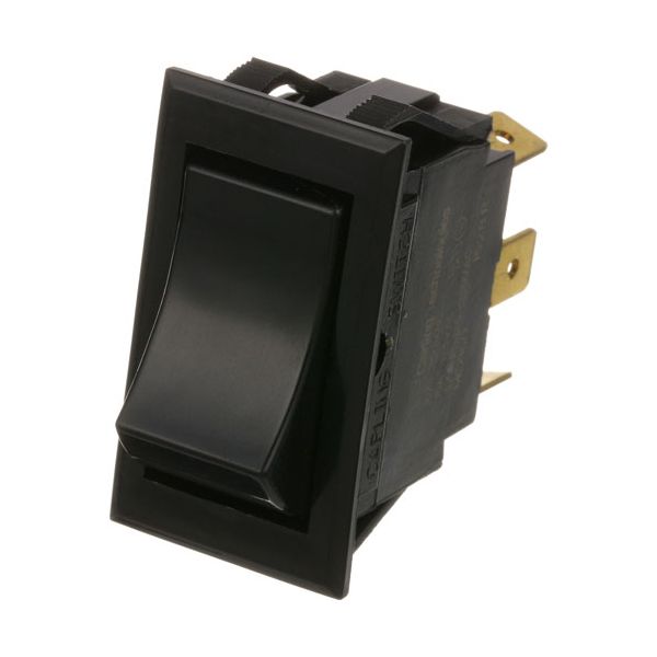
Dynamic Cooking Systems 16087-3 Oven SPDT Fan Switch 7/8" X 1-1/2"

Special Price $42.21 Regular Price $101.19
Out of stock
SKU
16087-3
The Dynamic Cooking Systems 16087-3 SPDT Fan Switch represents a vital component which improves operational capabilities of ovens. The robust rocker switch operates as a single-pole double-throw partwith three 1/4" tabs while maintaining a 7/8" x 1-1/2" dimensions. The partfits multiple oven systems including Cleveland Steamer Convection Steamers 21-CET-8, 21-CET-16, ICV, ICVD and DCS Oven FSCO. The switch operates at 10A at 250V and 15A at 125V while maintaining durability and safety requirements for demanding cooking applications.

Dimensions

  • Length: 1.875 In
  • Width: 1.75 In
  • Height: 1 In
  • Weight: 0.1 lbs
https://partsfe.com/media/catalog/product/d/y/dynamic-cooking-systems-16087-3-oven-spdt-fan-switch-7-8-x-1-1-2-59034-2.jpg

Product Notes

  • Rocker Switch, Spdt (On-On), 3 Tabs 1/4", Black,
  • 10A-250V, 15A-125V Rocker, 7/8" X 1-1/2",
  • Cleveland Steamer Convection Steamer: 21-Cet-8, 21-Cet-16.
  • Imperial Oven Series: Icv, Icvd.
  • Dcs Oven Fsco.
  • Southbend Oven Eb/Eh, Sleb/Eh
DYNAMIC COOKING SYSTEMS:
16087-3, DCS16087-3
IMPERIAL:
ROYAL RANGE:
SOUTHBEND:
Write Your Own Review
You're reviewing:Dynamic Cooking Systems 16087-3 Oven SPDT Fan Switch 7/8" X 1-1/2"
Your Rating
Customer Questions
What maintenance is required for the Dynamic Cooking Systems 16087-3 Fan Switch?

Inspect the oven fan switch periodically for secure connections and signs of damage or overheating. Keep surrounding components clean and free from grease buildup. Proper maintenance ensures accurate switching performance, prevents electrical faults, and support better operation of the oven’s fan system.

What are common issues with the Dynamic Cooking Systems 16087-3 Fan Switch?

  • Oven switch failing to toggle between positions.
  • Intermittent fan operation.
  • Loose or damaged electrical connections.
  • Overheating or burnt contacts.
  • Unresponsive switch due to internal damage.

We strive to provide our customers with a hassle-free and efficient shopping experience. Our shipping policy ensures the timely delivery of your orders and complete customer satisfaction. View More

We are committed to ensuring your complete satisfaction with every purchase. We understand that circumstances may arise where you must return a product or request a refund. If for any reason you are not satisfied, you may return the item(s) according to the terms outlined below. View More

This Payment Policy outlines the terms and conditions governing all payments made for products purchased through our website. By making a purchase, you agree to be bound by this Payment Policy. View More

Installation Steps

Step1: Disconnect electrical power at the breaker and confirm no voltage is present before servicing.

Step2: Remove control panel to access the fan switch and note all wire positions.

Step3: Detach old switch from mounting cutout and disconnect terminals.

Step4: Install new switch into the opening and secure it firmly in place.

Step5: Reconnect wires to matching terminals ensuring tight, correct SPDT configuration.

Step6: Restore power and test fan operation through all switch positions before returning to service.