
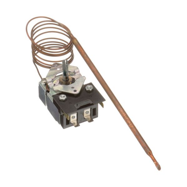
Duke 2081-2 KA Thermostat W/ 1/4" X 7-9/16" Bulb, Auxillary Switch

Special Price $104.52 Regular Price $206.00
In stock
SKU
2081-2
Manufacturer:

The Duke 2081-2 KA Thermostat with a 1/4″ x 7-9/16″ bulb and auxiliary switch is a multi-purpose temperature control part for the steam tables such as the SUB-FC-206-RT Subway. Having a temperature control of 140°F to 500°F, it provides the necessary heat control for food service equipment. The 48-inch cap is convenient in installation, and the auxiliary switch is extra for the user. This thermostat improves performance by regulating temperature to avoid fluctuating temperatures that wastes energy easing kitchen operations and food preservation.

Dimensions

  • Length: 8 In
  • Width: 2.5 In
  • Height: 2.5 In
  • Weight: 0.8 lbs
https://partsfe.com/media/catalog/product/d/u/duke-2081-2-ka-thermostat-w-1-4-x-7-9-16-bulb-auxillary-switch.jpg

Product Notes

  • [ Type - Ka ] [ Temp 140-500 ] [ Bulb 1/4" X 7-9/16" ]
  • [ Cap 48" ] Has Auxillary Switch.
  • [ Mount 1 ][ Dial Use # 22-1262 ]
  • Duke Steam Tables Aerohot, Thurmaduke.
  • Prep Table Sub-Fc-206-Rt (Subway)
DUKE:
2081, 2081-2, 212081, DUK212081
U-LINE:
5300-02G, KA-604-24, KA604-24
Write Your Own Review
You're reviewing:Duke 2081-2 KA Thermostat W/ 1/4" X 7-9/16" Bulb, Auxillary Switch
Your Rating
Customer Questions
What maintenance is required for the Duke 2081-2 KA Thermostat Bulb Auxillary Switch?

Check the thermostat bulb for proper positioning and any physical damage. Ensure wiring connections remain tight and free from corrosion. Periodically verify temperature accuracy and inspect the auxiliary switch operation. Always disconnect power before handling electrical components to prevent hazards.

What are common issues with the Duke 2081-2 KA Thermostat Bulb Auxillary Switch?

  • Inconsistent or incorrect temperature regulation.
  • Thermostat failing to activate or shut off equipment.
  • Bulb losing sensitivity or becoming damaged.
  • Loose wiring causing intermittent operation.
  • Auxiliary switch not engaging properly.

We strive to provide our customers with a hassle-free and efficient shopping experience. Our shipping policy ensures the timely delivery of your orders and complete customer satisfaction. View More

We are committed to ensuring your complete satisfaction with every purchase. We understand that circumstances may arise where you must return a product or request a refund. If for any reason you are not satisfied, you may return the item(s) according to the terms outlined below. View More

This Payment Policy outlines the terms and conditions governing all payments made for products purchased through our website. By making a purchase, you agree to be bound by this Payment Policy. View More

Installation Steps

Step1: Isolate power supply to equipment and verify zero voltage using a multimeter and apply lockout tagout procedure.

Step2: Remove existing thermostat and label wiring connections carefully before disconnection.

Step3: Mount thermostat bulb into sensing location and secure bracket firmly.

Step4: Connect wiring to terminals including auxiliary switch per wiring diagram securely.

Step5: Restore power and test temperature control operation and safety cutoff operation.