Groen NT1067 3-Pole Contactor 30/40A 208/240V

Special Price $68.94 Regular Price $89.53
In stock
SKU
NT1067
Manufacturer:
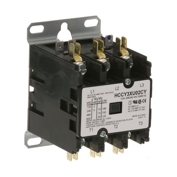
The Groen NT1067 3-pole contactor helps control electrical circuits reliably, with a strong and space-saving build that works well in many settings. The contactor works with 3 contacts, can handle 30/40 amps of current, and works with 208/240-volt power. This contactor works well and stays reliable, taking up little space in electrical panels and making system integration easier during installation. This contactor works well in three main areas: controlling motors, turning on big lights, and directing power to different places.

Dimensions

  • Length: 3.125 In
  • Width: 3.875 In
  • Height: 2.5 In
  • Weight: 1.5 lbs
https://partsfe.com/media/catalog/product/g/r/groen-nt1067-3-pole-contactor-30-40a-208-240v-66845.jpg

Product Notes

  • Hartland Contactor, 3 Pole, 208/240 Volt
  • 30 Amp Inductive, 40 Amp Resistive
  • Blodgett
  • Cleveland Kettle Kep, Kel, Kel-T, Sse-L,
  • Sse-T ( Standard Kettles Only )
  • Skillet Sel-40, Sem-40, Set-15.
  • Groen Steamer
  • Hatco Boosters
  • Hubbel Booster
  • Imperial Series: Ifse, Itge, Series: Icv-E
  • Legion Kettle
  • Market Forge Fryer Dffe, Kettle
  • Market Forge Electric Steam Generators
  • Star Fryer
  • Stero Dishwasher
Write Your Own Review
You're reviewing:Groen NT1067 3-Pole Contactor 30/40A 208/240V
Your Rating
Customer Questions
What maintenance is required for the Groen NT1067 Contactor?

Inspect terminals regularly for looseness and signs of arcing, and tighten connections as needed. Keep the contactor clean and free of dust or debris to ensure accurate switching. Periodically check coil operation and replace if intermittent performance occurs. Always disconnect power before servicing to ensure safety.

What are common issues with the Groen NT1067 Contactor?

  • Contact welding causing continuous power flow or stuck contacts.
  • Coil failure leading to no switching response.
  • Overheating from overloaded current causing nuisance trips.
  • Intermittent operation due to worn contacts.
  • Voltage fluctuation causing inconsistent operation.

We strive to provide our customers with a hassle-free and efficient shopping experience. Our shipping policy ensures the timely delivery of your orders and complete customer satisfaction. View More

We are committed to ensuring your complete satisfaction with every purchase. We understand that circumstances may arise where you must return a product or request a refund. If for any reason you are not satisfied, you may return the item(s) according to the terms outlined below. View More

This Payment Policy outlines the terms and conditions governing all payments made for products purchased through our website. By making a purchase, you agree to be bound by this Payment Policy. View More

Installation Steps

Step1: Disconnect main power and verify zero voltage before servicing to prevent electrical shock.

Step2: Open control panel and locate the existing contactor assembly in the electrical section.

Step3: Label and disconnect coil and load wiring carefully to ensure correct reconnection.

Step4: Remove mounting screws and replace with the new contactor in the same position.

Step5: Reconnect all terminals securely and inspect for proper tightness.

Step6: Restore power and test operation for correct switching and heating control.