
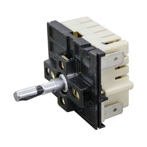
Garland GLG03185-2 Infinite Heat Switch

$89.90
In stock
SKU
GLG03185-2
Manufacturer:
Infinite Heat Switch

Dimensions

  • Length: 2 In
  • Width: 2 In
  • Height: 2.5 In
  • Weight: 0.2 lbs
https://partsfe.com/media/catalog/product/g/a/garland-glg03185-2-infinite-heat-switch-54063-2.jpg

Product Notes

  • 240V/15A )( Infinite ), Terminal( 5~
  • 1/4" Tab~
  • L1,L2(Line),P(Pilot),H1,H2(Load) )~
  • Contacts( N.O. )'
  • Style( Rotary )~
  • Markings( 1-10 )~
  • Shaft( 7/8" Lg~
  • .187" Flat Down )
  • Garland Grill Knob # 22-1395, Insert # 22-1402
  • Off-Min-2, 3, 4, 5, 6,-Max
  • Dial # 22-1012, Chrome Face
  • Middleby/Toastmaster Dial # 22-1072, Black
  • Ember-Glo & Gen Use Black Knob # 22-1349
  • 2" Dia, Off-Lo-2-6-Hi, Universal Mount, W/ 5 Inserts
  • Garland Range Series: 680.
  • Eagle/Metal Masters Warmer
  • Ember-Glo Broiler Series: E24.
  • Warmer C-240-2.Series: 1220(Cwd,Fwd,Fwe), Bpdht, Cdht,
APW WYOTT:
87053, APW87053
BLOOMFIELD:
EMBER GLO:
8425-20, 8425-65, 842520, EMB8425-20, EMB842520
LINCOLN:
MERCO:
MIDDLEBY MARSHALL:
SAVORY:
12355, 14702, 41096
U-LINE:
5502-317, INF240-472, INF240-577
Write Your Own Review
You're reviewing:Garland GLG03185-2 Infinite Heat Switch
Your Rating
Customer Questions
What maintenance is required for the Garland GLG03185-2 Infinite Heat Switch?

Inspect the switch regularly for loose connections and heat damage. Clean terminals to prevent carbon buildup and ensure smooth operation. Always disconnect power before servicing to avoid electrical hazards and ensure safe, accurate temperature control.

What are common issues with the Garland GLG03185-2 Infinite Heat Switch?

  • Overheating due to worn internal contacts.
  • Intermittent heating or inconsistent temperature control.
  • Switch failure from electrical arcing or burnt contacts.
  • Loose wiring connections causing power loss.
  • Failure to respond to heat settings changes.

We strive to provide our customers with a hassle-free and efficient shopping experience. Our shipping policy ensures the timely delivery of your orders and complete customer satisfaction. View More

We are committed to ensuring your complete satisfaction with every purchase. We understand that circumstances may arise where you must return a product or request a refund. If for any reason you are not satisfied, you may return the item(s) according to the terms outlined below. View More

This Payment Policy outlines the terms and conditions governing all payments made for products purchased through our website. By making a purchase, you agree to be bound by this Payment Policy. View More

Installation Steps

Step1: Disconnect power supply to avoid electrical shock.

Step2: Remove control panel cover to access the old switch.

Step3: Label and disconnect wires from the existing switch.

Step4: Unscrew and remove the faulty unit.

Step5: Install the new switch and secure with screws.

Step6: Reconnect wires to matching terminals.

Step7: Reassemble panel and restore power.

Step8: Test operation carefully.