
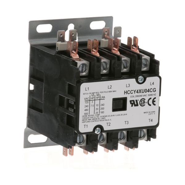
Garland 1026101 Contactor 4-Pole 40A Inductive/50A Resistive 208/240V

Special Price $93.01 Regular Price $150.84
In stock
SKU
1026101
Manufacturer:

The Garland 1026101 contactor is a commercial foodservice equipment electrical switching part with four poles that are operated at 208/240 volts. It works by switching and breaking several electrical circuits at the same time to regulate power supply to components rated at 40 amps inductive and 50 amps resistive loads. This contactor is applicable in cooking and heating devices that are usually used in restaurant and institutional kitchen settings in that it controls the flow of power between the incoming supply and internal electrical components in the normal operating cycles.

Dimensions

  • Length: 4 In
  • Width: 3 In
  • Height: 3 In
  • Weight: 1.27 lbs
https://partsfe.com/media/catalog/product/g/a/garland-1026101-4-pole-contactor-208-240v-40a-inductive-50a-resistive-86266-2.jpg

Product Notes

  • Hartland Contactor
  • 4 Pole
  • 208/240 Volt
  • 40 Amp Inductive
  • 50 Amp Resistive
  • Bki
Write Your Own Review
You're reviewing:Garland 1026101 Contactor 4-Pole 40A Inductive/50A Resistive 208/240V
Your Rating
Customer Questions
What maintenance is required for the Garland 1026101 Pole Contactor?

Regularly inspect and clean contact points to prevent arcing and carbon buildup. Tighten all electrical terminals to ensure stable connections and avoid overheating. Check coil condition and insulation for reliable switching. Always disconnect power before servicing to ensure safety.

What are common issues with the Garland 1026101 Pole Contactor?

  • Contact pitting or burning that leads to Less switching performance.
  • Coil failure causing the contactor not to energize.
  • Loose electrical connections resulting in intermittent operation.
  • Overheating due to excessive load or voltage fluctuations.
  • Chattering caused by unstable control voltage.

We strive to provide our customers with a hassle-free and efficient shopping experience. Our shipping policy ensures the timely delivery of your orders and complete customer satisfaction. View More

We are committed to ensuring your complete satisfaction with every purchase. We understand that circumstances may arise where you must return a product or request a refund. If for any reason you are not satisfied, you may return the item(s) according to the terms outlined below. View More

This Payment Policy outlines the terms and conditions governing all payments made for products purchased through our website. By making a purchase, you agree to be bound by this Payment Policy. View More

Installation Steps

Step1: Turn off power and lockout tagout to avoid electrical shock.

Step2: Remove control panel cover and document existing wiring.

Step3: Disconnect old contactor and mount unit securely.

Step4: Connect load and line terminals, match coil voltage.

Step5: Tighten connections, reassemble, restore power, test operation.