
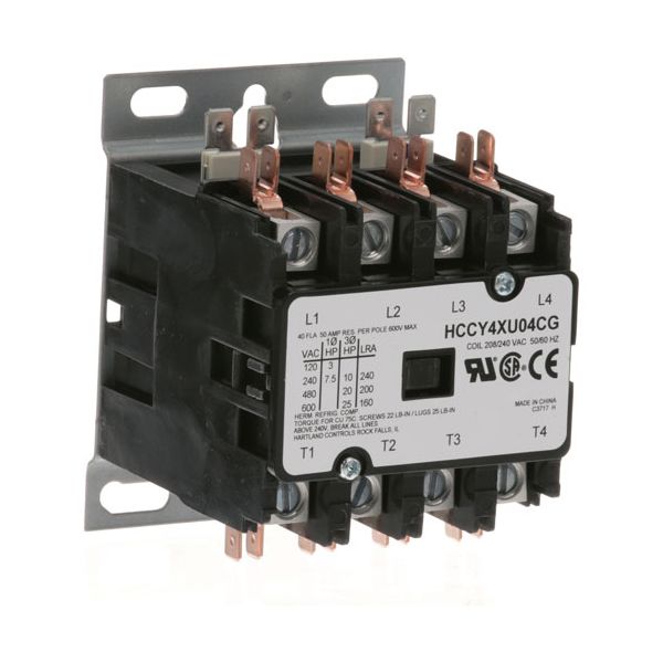
Groen GR13368 Contactor 4-Pole 40A/50A 208/240V

Special Price $93.01 Regular Price $150.84
In stock
SKU
GR13368
Manufacturer:

The Groen GR13368 Contactor 4-Pole 40A/50A 208/240V is an electrically controlled switch that opens and closes internal contacts that control the high-current flow of power to heating parts or motors. A magnetic field causes the 4-pole connection points to be drawn towards each other when a provided voltage signal is applied to the induction coil to complete the circuit and trigger the hardware connected to the circuit. The unit enables power distribution over a variety of lines and a current rating of 50A in a 208V to 240V system.

Dimensions

  • Length: 4 In
  • Width: 3 In
  • Height: 3 In
  • Weight: 1.27 lbs
https://partsfe.com/media/catalog/product/g/r/groen-gr13368-4-pole-contactor-208-240v-40a-inductive-50a-resistive-56063-2.jpg

Product Notes

  • Hartland Contactor
  • 4 Pole
  • 208/240 Volt
  • 40 Amp Inductive
  • 50 Amp Resistive
  • Bki
Write Your Own Review
You're reviewing:Groen GR13368 Contactor 4-Pole 40A/50A 208/240V
Your Rating
Customer Questions
What maintenance is required for the Groen GR13368 Contactor?

Inspect the contactor regularly for loose wiring, overheating marks, pitted contacts, or signs of electrical arcing. Keep the electrical enclosure clean and free of moisture, grease, and debris. Verify that terminal connections remain tight during routine equipment service. Disconnect power before inspection or replacement to prevent electrical shock hazards.

What are common issues with the Groen GR13368 Contactor?

  • Contacts sticking in the open or closed position.
  • Coil failure preventing contactor engagement.
  • Electrical arcing causing burned or pitted contacts.
  • Intermittent equipment heating due to poor contact connection.
  • Excessive buzzing or chattering during operation.

We strive to provide our customers with a hassle-free and efficient shopping experience. Our shipping policy ensures the timely delivery of your orders and complete customer satisfaction. View More

We are committed to ensuring your complete satisfaction with every purchase. We understand that circumstances may arise where you must return a product or request a refund. If for any reason you are not satisfied, you may return the item(s) according to the terms outlined below. View More

This Payment Policy outlines the terms and conditions governing all payments made for products purchased through our website. By making a purchase, you agree to be bound by this Payment Policy. View More

Installation Steps

Step1: Turn off and lock out main power supply completely and verify absence of voltage.

Step2: Verify voltage compatibility before installation as specified.

Step3: Mount contactor securely on DIN rail or panel enclosure properly aligned.

Step4: Connect line and load terminals per wiring diagram carefully following label markings.

Step5: Tighten terminals securely and check insulation resistance using meter.

Step6: Restore power and test switching operation thoroughly under no-load first.

Step7: Ensure enclosure is closed for safety compliance and proper operation.