
Hobart 00-821078 Ignition Control Module 24V F429 Ca-145

Special Price $197.79 Regular Price $387.03
In stock
SKU
00-821078
Oven Parts, Ignitors,
Manufacturer:

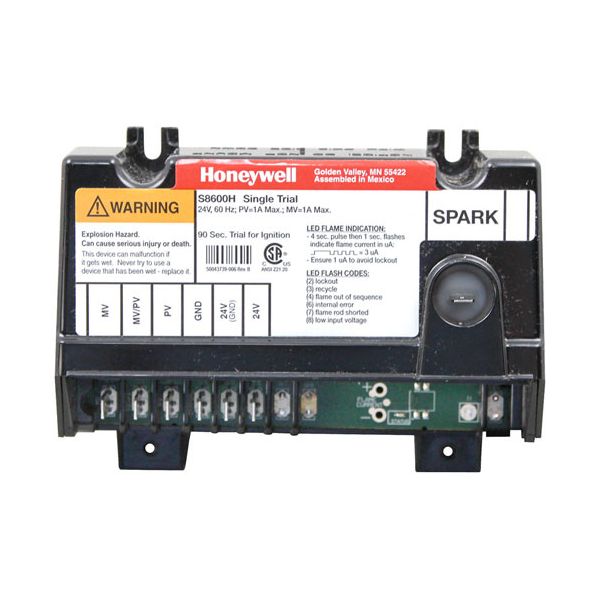
The Hobart 00-821078 Ignition Control Module is a high performance 24V device for commercial cooking equipment, used in Groen kettles and Marshall Air broilers as well as Vulcan Hart appliances. This module controls the gas burner ignition process, efficiently controlling the spark and reliable ignition of natural and LP gas systems. The module has a sleek black box design with spark connection on top, and has multiple connection points for easy installation, including MV, PV, GND and spark.

Dimensions

  • Length: 5.5 In
  • Width: 4 In
  • Height: 2 In
  • Weight: 0.75 lbs
https://partsfe.com/media/catalog/product/h/o/hobart-00-821078-ignition-control-module-24v-f429-ca-145-61652-2.jpg

Product Notes

  • Ignition Control Module 24V, F429, Ca-145, # 441283
  • S8600H3002,
  • 1 Mv, 2 Mv/Pv, 3 Pv,
  • 4 Gnd(Burner), 5 24V(Gnd), 6 24V, 9 Spark, 90 Sec
  • New/Style Black Box W/ Spark Connection On Top
  • Groen Kettle, Marshall Air Broiler.
  • For Vulcan Hart:
  • Nat/Lp Pilot, H501, # 51-1467
  • Ignition Cable, Vul419359 (Non-Stock)
  • Vulcan Model 1Gr45M, 1Gr65M, 1Gr85M, 1Grc35, 1Grc45,
  • 1Grc65,1Grd45, 1Grd65, 1Grs35, 1Grs45, 1Grs65, Ef3, Ef4,
  • Ef5, G40Tb, Gr35,Gr35F, Gr45, Gr45F, Gr65, Gr65F, Gr85,
  • Gr85F, Grc35F,Grc45F, Grc65F, Grc85F, Grd35F, Grd45F,
  • Grd65F, Grd85F,Grs35F, Grs45F, Grs65F, Grs85F
Write Your Own Review
You're reviewing:Hobart 00-821078 Ignition Control Module 24V F429 Ca-145
Your Rating
Customer Questions
What maintenance is required for the Hobart 00-821078 Ignition Control Module?

Inspect ignition control module for dust, moisture, and loose wiring connections. Keep terminals clean and ensure proper grounding. Verify stable voltage supply to maintain consistent ignition and safe burner operation.

What are common issues with the Hobart 00-821078 Ignition Control Module?

  • No ignition response in Hobart equipment during startup.
  • Electrical component burnout from power fluctuations.
  • Loose or corroded wiring connections.
  • System shutdown due to overheating or fault lockout.

We strive to provide our customers with a hassle-free and efficient shopping experience. Our shipping policy ensures the timely delivery of your orders and complete customer satisfaction. View More

We are committed to ensuring your complete satisfaction with every purchase. We understand that circumstances may arise where you must return a product or request a refund. If for any reason you are not satisfied, you may return the item(s) according to the terms outlined below. View More

This Payment Policy outlines the terms and conditions governing all payments made for products purchased through our website. By making a purchase, you agree to be bound by this Payment Policy. View More

Installation Steps

Step1: Disconnect power and gas supply, use lockout/tagout if available.

Step2: Remove access panel to reach control module carefully.

Step3: Label and disconnect wiring harness from old module.

Step4: Mount new module securely in same position.

Step5: Reconnect wiring exactly as original diagram.

Step6: Inspect all connections for tightness and correct routing.

Step7: Restore power and test ignition cycle.