
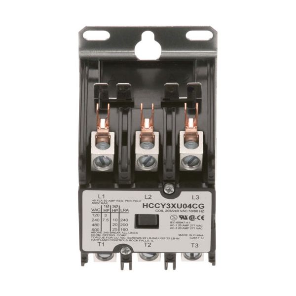
Cleveland KE50750 Contactor 3-Pole 40/50A 208/240V

Special Price $68.86 Regular Price $106.11
In stock
SKU
KE50750
Manufacturer:

The Cleveland KE50750 Contactor 3-Pole 40/50A 208/240 V is a part that uses electromagnetic coils to switch electrical circuits on and off to enable the flow of current to be controlled to the part connected to it. The three poles are connected to different circuits, and coordinating the switching of multi-phase systems is possible. It is intended to be installed within the electrical panel of a commercial kitchen, usually within the control section, where it will provide a centralized control of power to heating components, motors or other parts.

Dimensions

  • Length: 4 In
  • Width: 2.5 In
  • Height: 3.25 In
  • Weight: 1.06 lbs
https://partsfe.com/media/catalog/product/c/l/cleveland-ke50750-hartland-contactor-3p-40-50a-208-240v-15887.jpg

Product Notes

  • Hartland Contactor, 3 Pole
  • 208/240 Volt, 40 Amp Inductive, 50 Amp Resistive
  • Blickman Coffee Bk-2, Bk-22 C/C, Bk-33 C/C,
  • Blodgett
  • Cecilware Fryer Efp(30,40,65), Efs(30,40,65)
  • Cres-Cor Food Warmers, Top Mount 6000 & 8000 Watt Units
  • Hatco Booster
  • Henny Penny Fryer 561, 580, 581, Oe 301,302,303
  • Rotisserie Scr 6/8
  • Hubbel Booster
  • Keating 14 Bb Wosa,14 Ts Wosa,14Bb,14Ts,18 Bb Fm-E,18 Ts
  • Fm-E,20 Bb Fm-E,20 Ts Fm-E,2005,24 Bb Fm-E,34 Bb Fm-E,34 Ts
  • Fm-E,Bb,Electricfryerpre2000,Mg-2,Mg-4,Top-Side,Top-Side
  • Cooker,Topsidecooker2005,Ts
  • Legion Kettle
Write Your Own Review
You're reviewing:Cleveland KE50750 Contactor 3-Pole 40/50A 208/240V
Your Rating
Customer Questions
What maintenance is required for the Cleveland KE50750 Hartland Contactor?

Inspect and clean electrical contacts to prevent arcing and buildup. Tighten terminal connections and check for overheating signs. Ensure coil voltage is stable at 208/240V during operation. Regular inspection of enclosure can reduce dust accumulation and connection issues.

What are common issues with the Cleveland KE50750 Hartland Contactor?

  • Contact pitting or erosion causing intermittent switching.
  • Coil failure leading to non-engagement.
  • Loose terminals causing overheating or power loss.
  • Voltage fluctuation causing chatter.
  • Contactors sticking due to worn mechanical components.

We strive to provide our customers with a hassle-free and efficient shopping experience. Our shipping policy ensures the timely delivery of your orders and complete customer satisfaction. View More

We are committed to ensuring your complete satisfaction with every purchase. We understand that circumstances may arise where you must return a product or request a refund. If for any reason you are not satisfied, you may return the item(s) according to the terms outlined below. View More

This Payment Policy outlines the terms and conditions governing all payments made for products purchased through our website. By making a purchase, you agree to be bound by this Payment Policy. View More

Installation Steps

Step1: Turn off main power and verify no voltage with tester before starting.

Step2: Mount contactor securely in enclosure on DIN rail or panel.

Step3: Connect line and load terminals per wiring diagram, tighten screws.

Step4: Attach control coil wiring for supply with correct polarity if required.

Step5: Add safety ground connection and ensure insulation is intact.

Step6: Restore power and test operation for proper switching operation.

Step7: Check for overheating, noise, or loose connections during initial run.